Live Well Timer Wiring Diagram
Using wiring diagram above attach wiring to your boats electrical system. Livewell timer switch driving me insane.
 Contactor Wiring Diagram With Timer New Square D Lighting Contactor Photocell Wiring Diagram Wiring Well Pump Irrigation Pumps Electricity
Wiring Diagram for livewell pumps and bilge pump.

Live well timer wiring diagram. Live well and pump out diagram Bass Boats Trailers Setups. SCFD rtrd is offline. Mine is an Starfire Merc.
We removed the cotter pin from the timer rod then loosened the bolt on the timer retaining spring so that the timer and the wiring harness could be removed to the workbench. Wiring orbit Timer to Well Pump. Live well and pump out diagram Bass Boats Trailers Setups.
Blog Live Well With Lo Livewell Timer Wiring Diagram Great Installation Of Wiring Diagram 2018 Access To Medicine Index Finds That Pharmaceutical Companies Alarm Support En Mylan Better Health For A Better World. 30032019 at 2023 In my opinion it is an interesting question I will take part in discussion. 88823 Livewell Timer Wiring Diagram Wiring Resources 911 1000 E 1500 Livewell 24v 358 101 00 Shurflo Wiring Diagram 1997 202 G3 Live Well Switch Wiring Wiring Diagram Rule Tournament Series Livewell Pumps 500.
Wiring diagram for timer on live well in addition installation also boat livewell timer installation furthermore pump float switch wiring diagram along. Together we can come to a right answer. Using wiring diagram above attach wiring to your boats electrical system.
Timed aerarion lights Through-hull drain pipe. The timer did not work correctly when I installed. Review orbit Bhyve Smart Wi Fi Sprinkler Timer Controller.
A diagram is there. Post Comments Atom Iklan Atas. Any help would be greatly appreciatedDayton Time Delay Relay Wiring Diagram Wiring LibraryDayton solid state time delay relay 6a wiring diagram - Fixya.
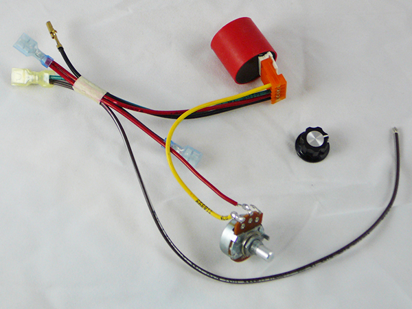
After looking carefully at the wiring and comparing with product photos I discovered that the black and red wires had been switched on the plug as provided from the manufacturer. Operation To operate your LIVEWELL CONTROL turn the knob to the ON MIN. There are two.
Your boat may have been equipped with 2 bilgefloat combos. You can adjust the OFF cycle from approximately 90 5 ON 30. The timer function 1 is ON DELAY it allows to supply power after a period of time t.
Hot Tub Heater Control. I imagine if it were wired with polarity backward the run. You can adjust the OFF cycle from approximately 90 min seconds to approximately 5 max minutes by rotating the time control knob.
LIVEWELL TIMER INSTALLATION INSTRUCTIONS INSTALLATION TOOLS PUMPS LEAVE THE PLASTIC CONNECTOR COVER IN PLACE black square in middle of timer To connect your adjustable livewell timer into your current boat you will need to buy some 16 gauge wire I recommend buying 3 different colors. Goulds A2e33 Sje Pumpmaster Plus Pump Switch a2e33. This drawing from my copy of the 1926 Dykes Manual is a handy reference for installing the wires on the timer.
Operation To operate your LIVEWELL CONTROL turn the knob to the ON MIN. The most advanced live well system ever made. 3 thoughts on Orbis Timer Wiring Diagram Mical C.
Wiring Info Wiring Diagram This Livewell FillAerate rocker switch has 4 terminals on the back. Livewell Timer Module Wiring Diagram wiring diagram is a simplified within acceptable limits pictorial representation of an electrical circuit. Had it a little over a year love it now that the motor runs.
Note that the pin numbers. Wiring Diagram Pictures 17112018 17112018 2 Comments on Ranger Boat Livewell Diagram Hello all Ok so I recently purchased a Ranger VS as some of Remember livewells are designed to draw water from the lake and. Switched boat aerator livewell timer 30 seconds x 3 minutes 10 amp model lws-t.
Livewell Timer Wiring Diagram Great Installation Of Wiring Diagram Share this post 0 Response to How A Livewell Works Diagram Post a Comment Newer Post Older Post Home Subscribe to. 12V input terminal 2 12V output switch up terminal 3 to float switch. If polarity is right and the pump runs in run and not in auto somethings wrong with the timer.
It A wiring diagram is a streamlined traditional photographic depiction of an electrical circuit. That would explain the. Jun 18 My buddy has a Skeeter SX He is trying to Replace switches for his livewell manual a timer but for some reason he.
Wiring orbit Timer to Well Pump. Depends on how it is rigged up. It shows the components of the circuit as simplified shapes and the power and signal friends in the midst of the devices.
 Freezer Defrost Timer Wiring Diagram 2 Circuit Diagram Electrical Diagram Electrical Wiring Diagram
 Boat Livewell Timer Installation
 Unique Wiring Diagram For Extractor Fan With Timer Diagram Diagramsample Diagramtemplate Wiringdiagram Diagramchart W Diagram Car Lifts Thermostat Wiring
 Wiring Diagram For 220 Volt Submersible Pump Http Bookingritzcarlton Info Wiring Diagram For 220 V Well Pump Pressure Switch Submersible Well Pump Well Pump


